Field Unit
Paula is a portable field unit that puts an ESP32 and a Raspberry Pi 3 on the same PCB. The ESP32 side has a 2.42″ OLED, ten status LEDs, buttons, LoRa, GPS, an RS485 port, sensor inputs and an RTC. The Pi 3 side adds Linux, USB ports and WiFi. It is hardware, and what it does is up to you. At Digital Stables we use it to carry firmware updates out to devices on the farm and flash them offline, and to test and calibrate sensors in the field. You might use it as a handheld data logger, a mapping tool, a LoRa gateway or something else entirely.
Paula doesn't have to be used this way. This is how we use it at Digital Stables, as an example of what the board can do. Our main use is updating firmware on devices out on the farm. Farms rarely have reliable network coverage, so Paula collects everything it needs at the office before the trip and keeps each result on the Pi until it is back on the network. The Pi software is open source (see the Software tab).
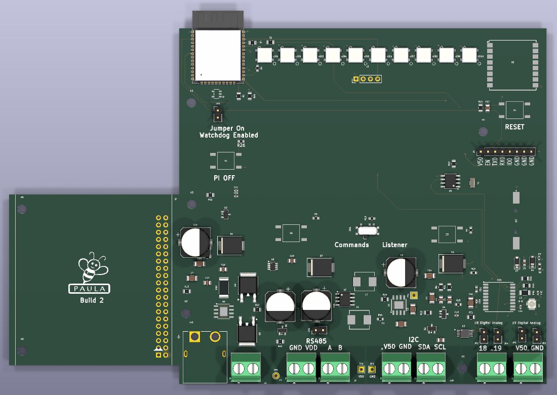
KiCad render of the unfinished Build 2 layout, 189 × 125 mm. The Raspberry Pi plugs upside-down into the 40-pin header on the left wing. The OLED module (not shown in the render) sits over the middle of the board.
| MCU | ESP32-WROOM-32E (8 MB) |
| Linux computer | Raspberry Pi 3, mounted upside-down; linked to the ESP32 by UART. A Pi Zero fits the same header (see below) |
| LoRa | Ra-02 SX1278, 433 MHz |
| GPS | u-blox MAX-M10S on I²C, u.FL antenna connector |
| RTC | PCF8563T with CR1220 coin-cell backup |
| Watchdog | CAT823 supervisor, enabled by jumper |
| Display | 2.42″ I²C OLED |
| Status LEDs | 10× WS2812B |
| Controls | Page buttons, Pi Off, Reset, Commands / Listener switch |
| Sensing | ADS1115 ADC, INA219 battery current, RS485 transceiver |
| Power | XT60 battery input; two TPS5430 buck regulators for 5 V and 3.3 V |
| Board size | 189 × 125 mm |
Flashing firmware needs a USB port for the device being updated. Paula also needs two WiFi connections: its own hotspot for your phone in the field, and the office network for syncing. The second one comes from a USB WiFi dongle, so Paula needs two USB ports. A Pi 3 has four. A Pi Zero plugs into the same 40-pin header, but its single USB port can't take both the device and the dongle.
Terminals along the bottom edge, labelled as on the Build 2 silkscreen.
| Silkscreen | Function |
|---|---|
XT60 | PWR Battery input |
GND VDD | PWR Battery voltage out, through a diode |
RS485 A B | RS485 Soil probe / Modbus sensor |
I2C SDA SCL | I²C External I²C sensors (shared bus) |
18 19 | Sensor Two sensor inputs, digital or analog (see jumpers) |
V50 GND (×2) | PWR 5 V for sensors |
V50 · EN · TX0 · RX0 · IO0 · GND · GND · GND, the same layout as Wally and Valentino.
| Jumper | Fitted |
|---|---|
| JP3 | Watchdog enabled: the CAT823 can reset the ESP32 |
| JP2 JP1 | Input 18 / 19 in digital mode, through a level shifter to GPIO18 / GPIO19 |
| JP4 JP5 | Input 18 / 19 in analog mode, to the ADS1115 |
| JP9 | 120 Ω RS485 bus termination |
ESP32 pin use from the current Build 2 schematic, for firmware reference. These assignments are preliminary and may change as the layout is finished.
| Signal | GPIO | Purpose |
|---|---|---|
SDA_I2C | 22 | I²C data. Swapped from the ESP32 default |
SCL_I2C | 21 | I²C clock. Swapped from the ESP32 default |
UART1_RX | 32 | From the Pi's UART TX |
UART1_TX | 33 | To the Pi's UART RX |
UART2 | 16 / 17 | RS485 transceiver (MAX485E) |
RS485_DERE | 23 | RS485 transmit enable |
GPIO_18 / 19 | 18 / 19 | Sensor inputs 18 and 19 (digital mode) |
WS2812B | 4 | Status LED data |
| Signal | GPIO | Purpose |
|---|---|---|
SCK / MISO / MOSI | 14 / 12 / 13 | Ra-02 LoRa SPI |
SS | 15 | LoRa chip select |
LORA_RST | 26 | LoRa reset |
LORA_DIO | 34 | LoRa interrupt (input-only pin) |
WATCHDOG_WDI | 25 | CAT823 watchdog input |
PI_OFF | 35 | Pi Off button (input-only pin) |
RTC_BATT_VOLT | 36 | Coin-cell voltage (SENSOR_VP) |
RTC_CLK_OUT | 39 | PCF8563T 1 Hz clock (SENSOR_VN) |
| Device | Address |
|---|---|
| 2.42″ OLED | 0x3C |
| INA219 battery current | 0x41 |
| u-blox MAX-M10S GPS | 0x42 |
| ADS1115 ADC | 0x48 |
| PCF8563T RTC | 0x51 |
The GPS supports I²C Fast-mode only, so run the bus at 320 kHz or slower.
This is the software we run on Paula at Digital Stables for field firmware updates. The two Pi programs are open source on GitHub. Use them as they are, adapt them, or start from scratch with your own code.
The command-line tool on the Pi. At the office it pulls pending deployments and firmware from the factory server. In the field it flashes devices with esptool. Back at the office it pushes the results. Its repository also has the script that sets up a new Pi, including the field WiFi hotspot.
GitHubA web app for your phone, served by the Pi over its own hotspot. It shows one tile per device waiting for an update, with a live flashing terminal. It can also Inspect a device, send it any command, and calibrate sensors.
GitHubThe ESP32 firmware. It drives the OLED pages, LEDs and buttons, listens to LoRa, reads the RS485 soil probe, and calibrates flow sensors. It also passes status between the Pi and the operator. Firmware for Build 2 is being written alongside the board.